Pylontech SC0500-100S BMS PowerCube X1/H1/H2
[ACC0884] Pylontech SC0500-100S BMS PowerCube X1/H1/H2
Para 2-10 módulos, altura: 3U
Sólo se suministra junto con las baterías correspondientes. , alternativa ACC01000
| Marca: Pylontech |
| Alto/largo producto (mm): 132mm |
Nombre mostrado:
[ACC0884] Pylontech SC0500-100S BMS PowerCube X1/H1/H2
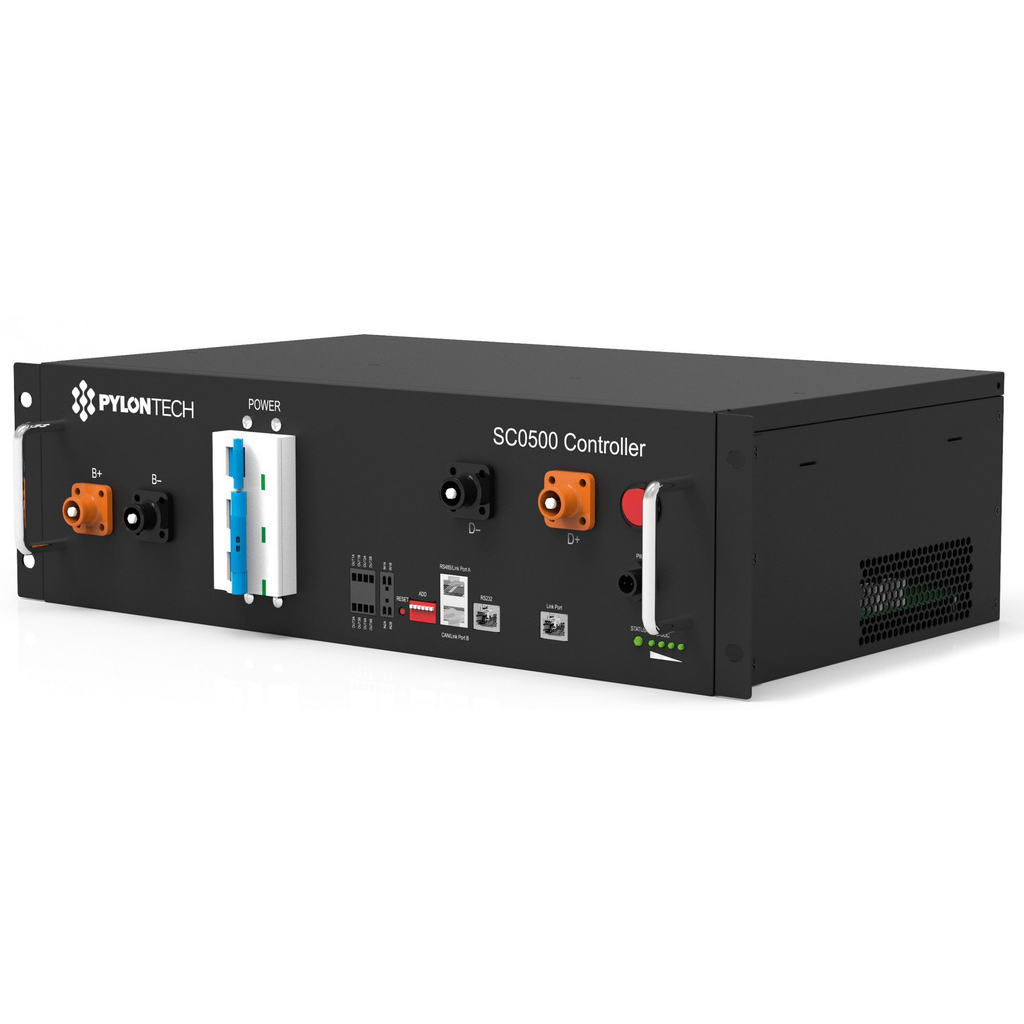
The Pylontech BMS SC500-100S controller is a voltage management system required for the connection of high voltage lithium batteries to the inverter.
This battery management system (BMS) is designed to have protection functions, even against excessive discharges, overloads, overpowers and high/low temperatures. It can automatically manage the state of charge and discharge and balance the current and voltage of each cell.
This control module has two types of power: internal power and external power.
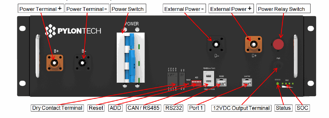
Power Termina +/- : To connect the battery supply cables in series.
Power Switch: Turns the battery system (control module and high voltage DC supply) on and off.
Please note that when the switch is triggered by overcurrent or short circuit, you must wait after 30 minutes to turn it on again, otherwise it may cause damage.
External Power Terminal +/- : Connect the battery system to the inverter.
Dry Contact Terminal: It provides a dry contact signal with 2 inputs and 4 outputs.
Reset: Reset button, press the button for a long time to reset the battery system.
Add: A 6-bit switch to manually distribute the communication address of the battery system. The losether position is OFF, meaning "0". The upper position in ON, means "1". For the BMS, the first bit to the 5th bit is for address assignment, and the 6th bit marking switch supports a 120Ω resistor.
Power Relay Switch: Normally it is set to ON position, it cannot be turned off in normal operation.
This power relay switch must be sure to be on. Otherwise, it will affect the automatic 10/15 18PIXP0801 testing process and cause danger.
You should not turn off the Power Relay Switch during normal operation condition, only in case of emergency it could be turned off directly. Otherwise, it will cause the current from this battery string to be triggered by another battery string.
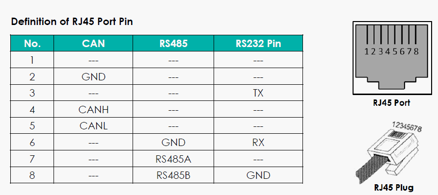
CAN / RS485: CAN communication terminal (RJ45 port) follows CAN protocol, for communication between battery system and inverter. RS485 communication terminal (RJ45 port) follows RS485 protocol, for communication between battery system and inverter.
RS232 Terminal: Console communication terminal (RJ45 port) follows RS232 protocol, so that the manufacturer or professional engineer can debug or service it.
Link Port 1: Link port 1 communication terminal (RJ45 port) follows CAN protocol, for communication between multiple serial battery modules and the control module.